


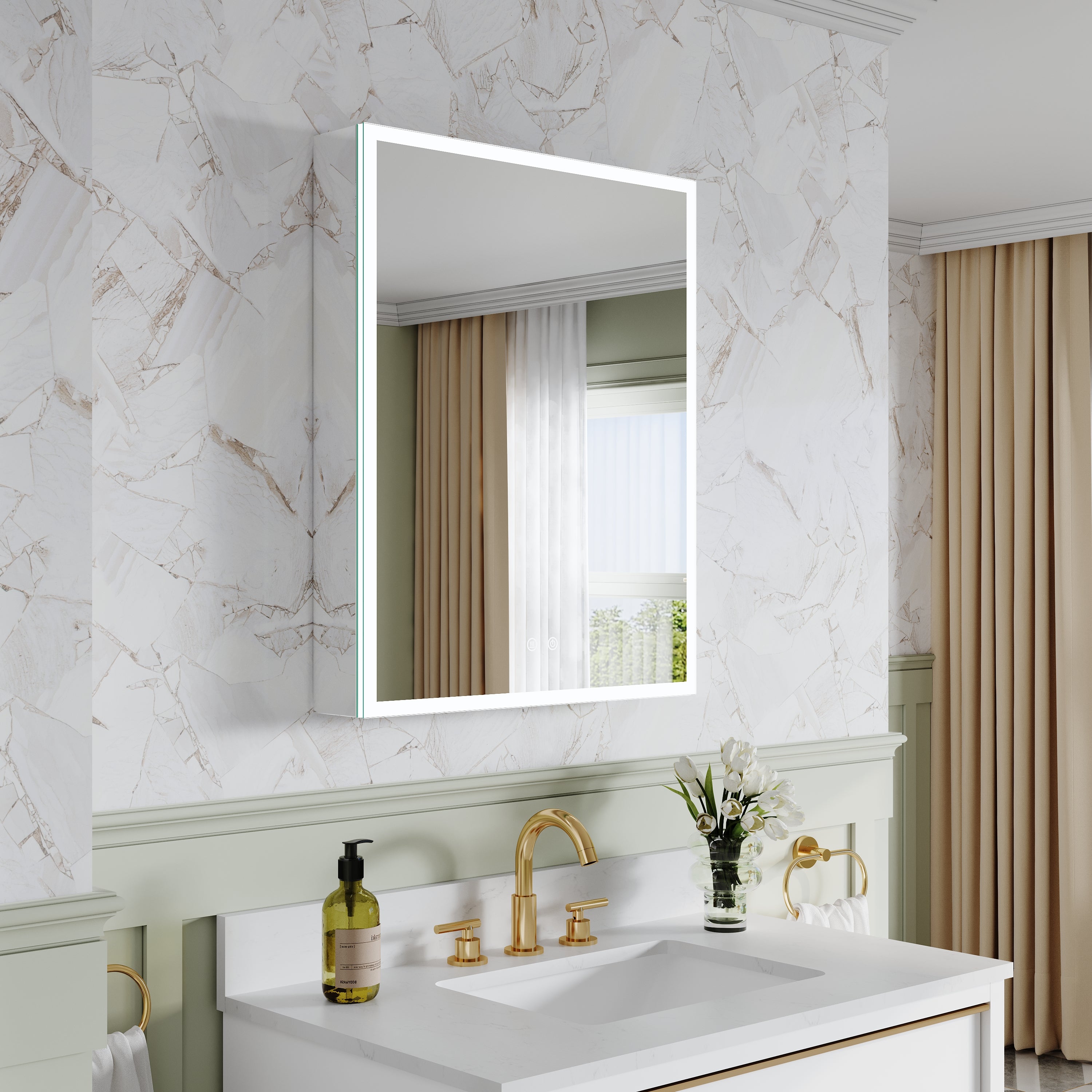
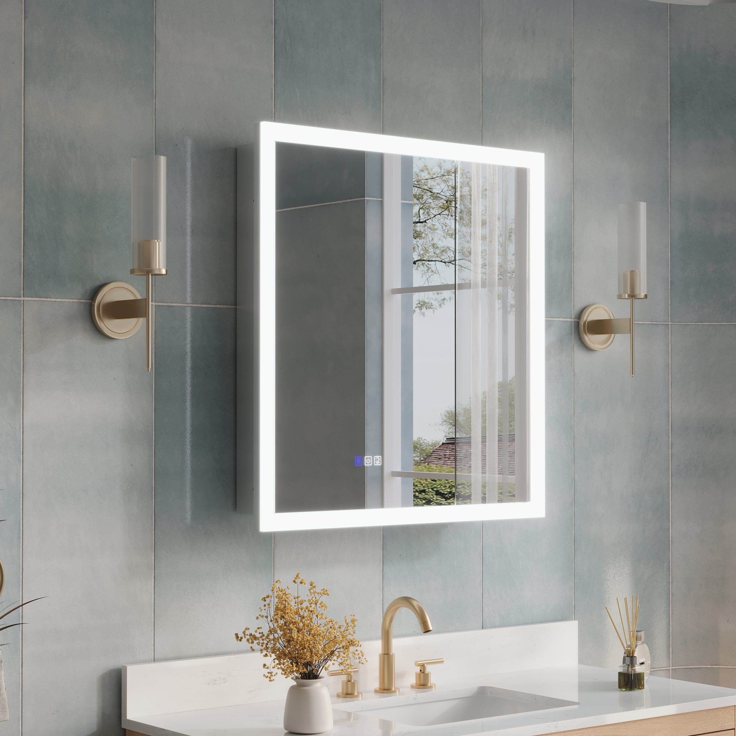
In the high-end bathroom renovation field in 2026, LED smart mirrors (Vanity Mirrors with LED Lights) are no longer just a decorative item hanging on the wall, but a core component of the electrical architecture in the wash area. With the popularization of defogging, Bluetooth audio, color rendering adjustment (CRI), and hand-scanning sensing technology, the power demand and wiring complexity of a smart mirror have far exceeded those of traditional lighting fixtures.
Many homeowners only realize in the later stages of renovation that the wall lines are not in the correct position or the power load is insufficient, resulting in the originally minimalist washing area being forced to have exposed lines or being unable to activate advanced functions. How to perfectly integrate vanity mirrors with LED lights into your electrical layout? This article will break down the industry-leading electrical integration standards of 2026 from seven professional dimensions, including circuit planning, safety protocols, switch linkage, and ergonomics.
1.The 'golden position' reserved for circuits: center point and concealment
The first step in electrical integration is to determine the precise coordinates of the wall outlet lines.
Coordinate calculation: Unlike ordinary wall lamps, the transformer of smart mirrors is usually hidden within the frame on the back of the mirror. The outlet point should be strictly aligned with the central reserved area behind the mirror to ensure that the mirror body completely covers the cable after the mirror is mounted.
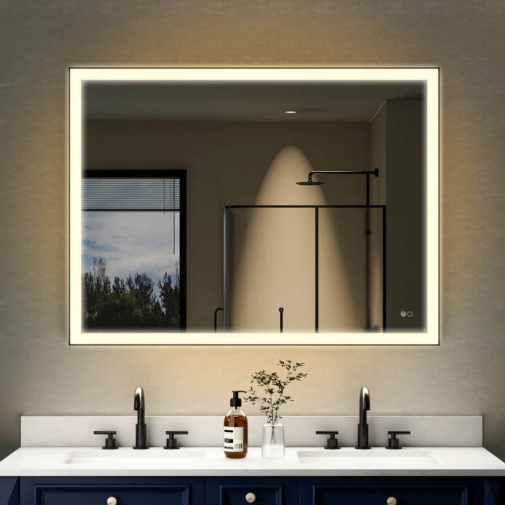
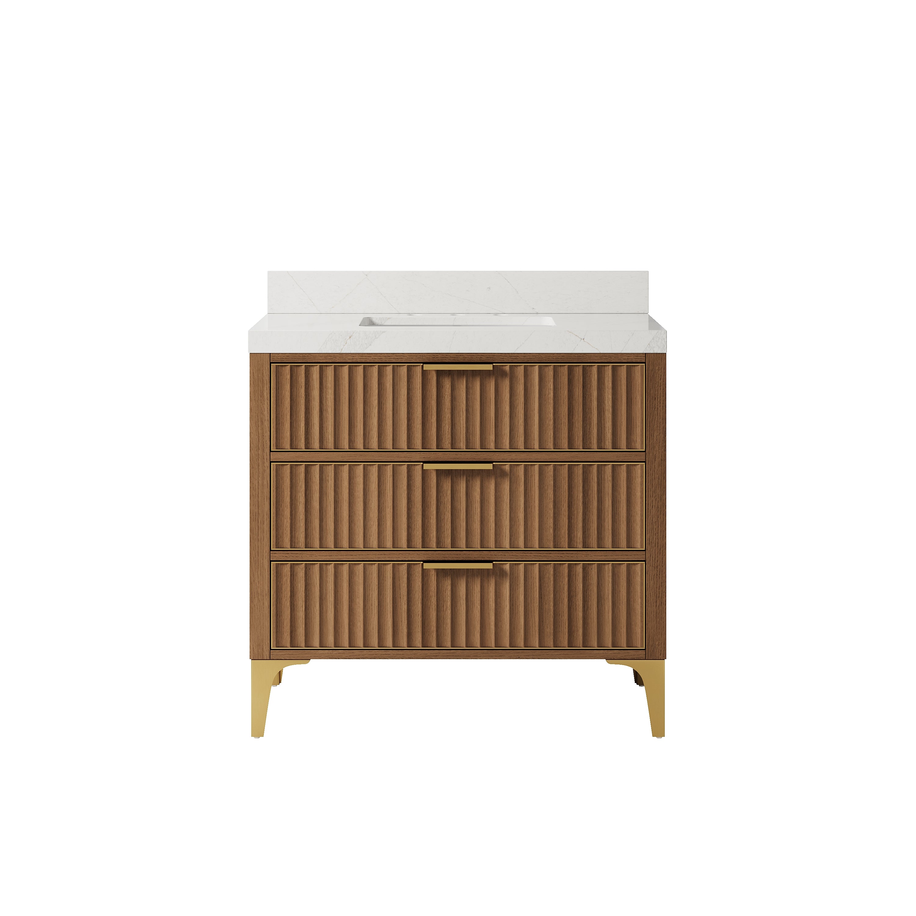
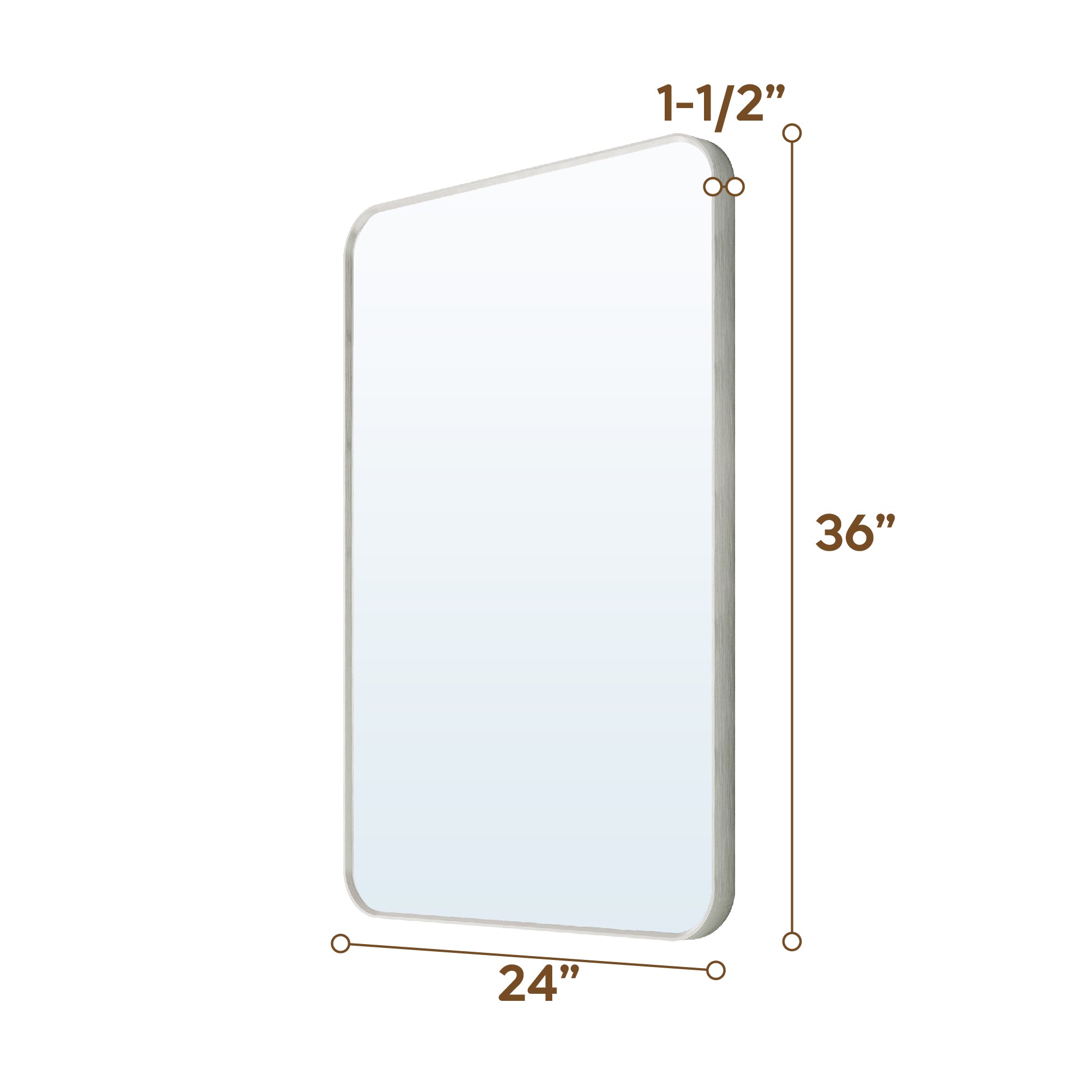
Vertical height: In conjunction with the installation of 36-inch vanities (36-inch bathroom cabinets), it is recommended to set the electrical outlet at a height of 60-65 inches (approximately 152-165 centimeters) above the ground to ensure that the cable length is sufficient to connect to the mirror back driver without affecting the stability of the pendant installation.
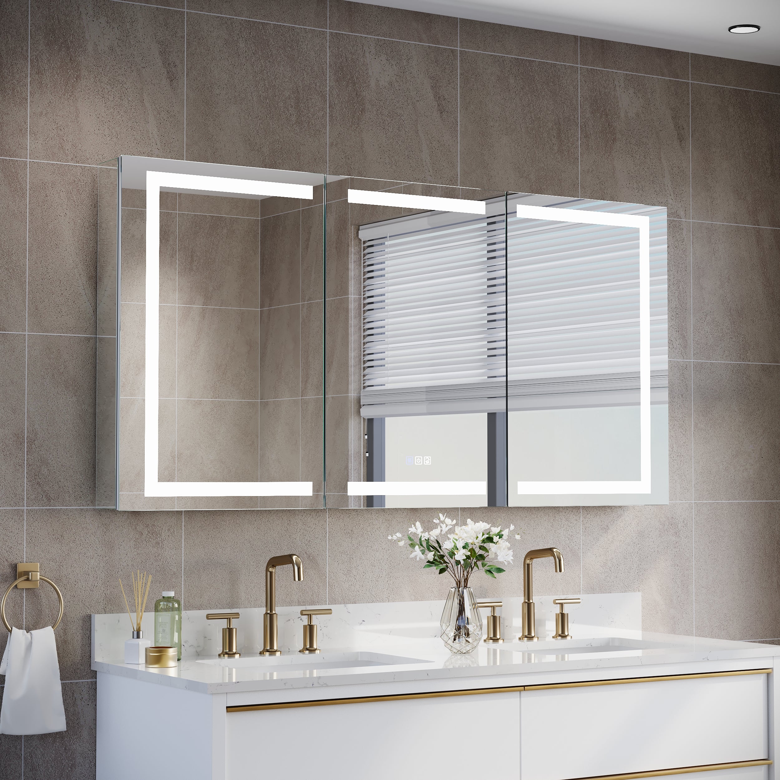
2.Power and load management: responding to the power demand of "multifunctional superposition."
In 2026, LED smart mirrors will no longer only consume a few watts of lighting power.
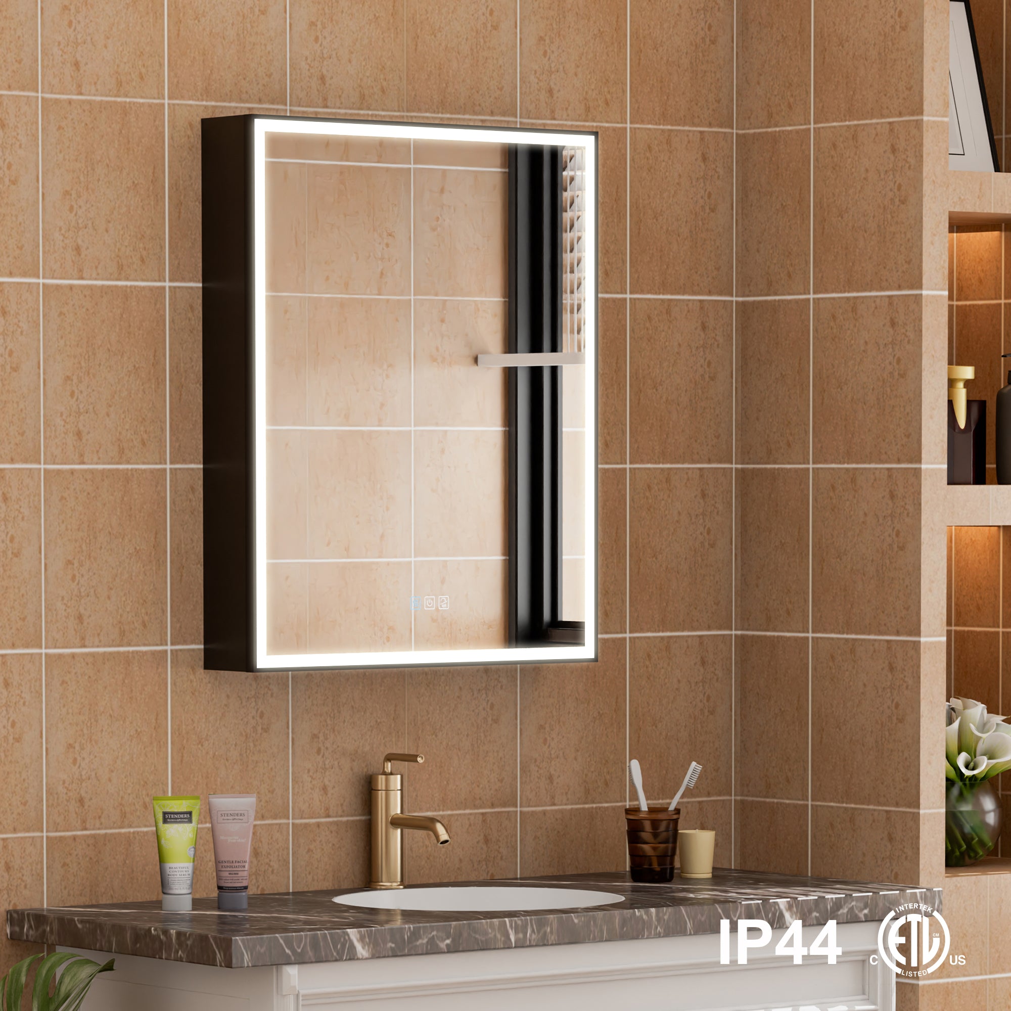
Power estimation: A 36-inch mirror with a large area of electric defogger film, a high-brightness LED light strip, and a built-in Bluetooth speaker may have a maximum operating power of 60W-100W.
Circuit planning: The industry recommends separating the lighting circuit in the washing area from the socket circuit (GFCI). Smart mirrors should be connected to the lighting circuit. Still, it is necessary to ensure that the circuit breaker of the circuit has sufficient amperage to avoid tripping when turning on the mirror defogger while using a hair dryer.
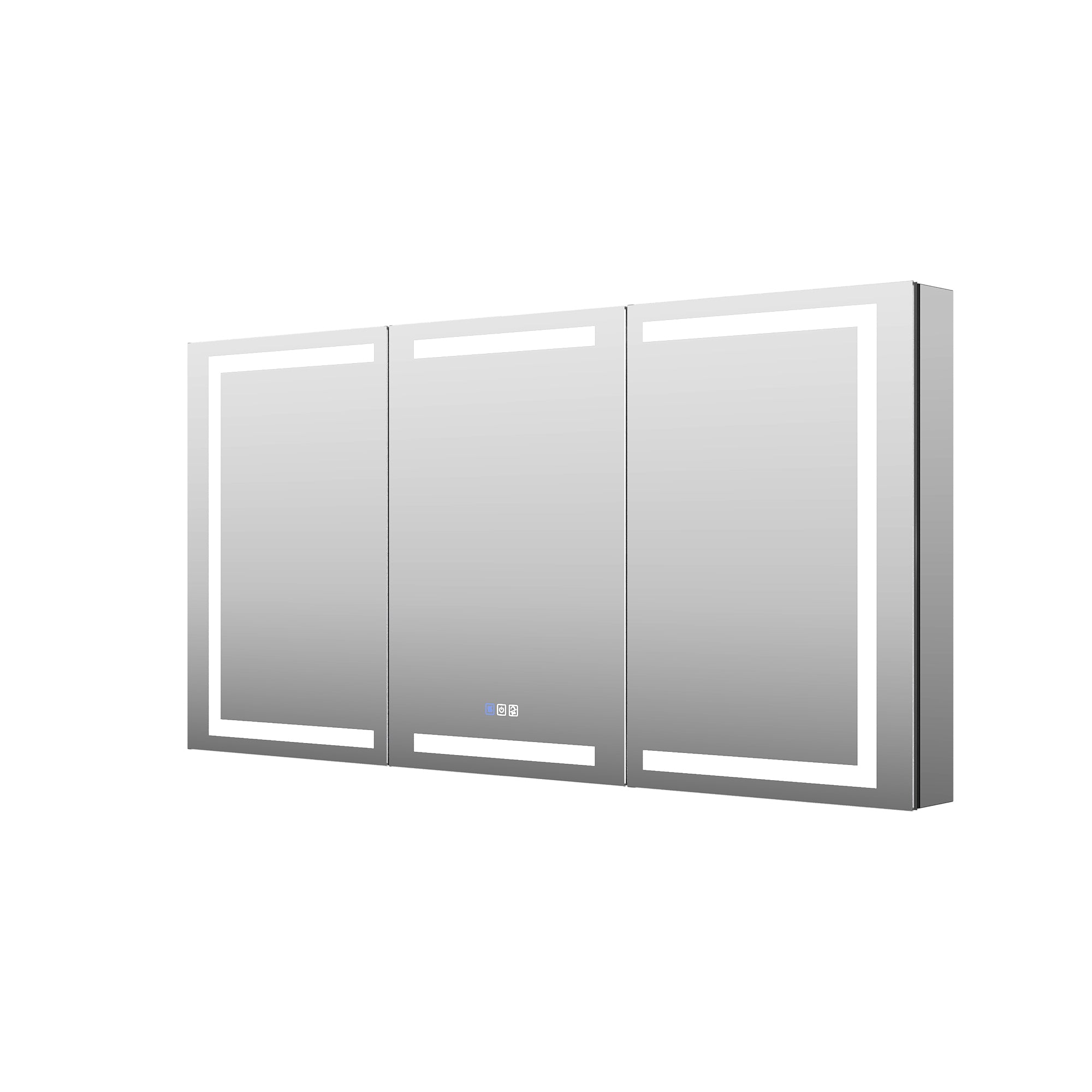
3.Linkage control logic: Hardwired and switch wall plug
In electrical layout, you need to decide how mirrors' wake up '.
Hardwired: This is standard for the 2026 refurbishment market. By directly connecting the cable to the junction box inside the wall, a visual system without visible wires can be achieved. Mirrors are usually controlled by independent physical switches on the wall to control the main power supply.
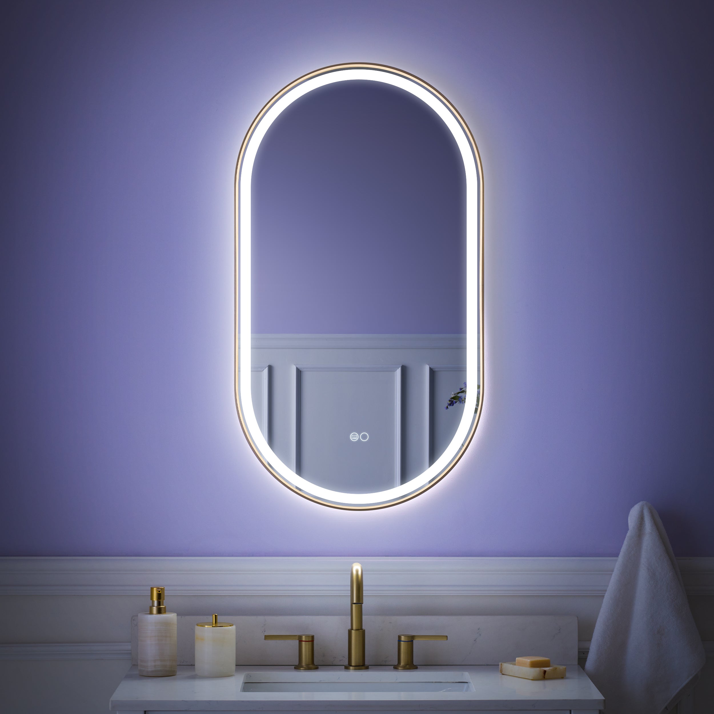
Linkage induction: The advanced solution is to link the basic lighting of the mirror with the main light of the bathroom. The hand sensor or touch screen that comes with the mirror is used for secondary brightness and color temperature adjustments, or to enable the defogging function. This dual logic ensures both the basic lighting for entering the room and provides flexibility for fine operations.
4.GFCI Security Protocol: Electrical Bottom Line in Wet Environments
The bathroom is the most demanding scene in electrical engineering.
Grounding protection: All installation points of LED smart mirrors must be protected by a GFCI (Ground Fault Current Leakage Protector). When arranging the electrical layout, ensure that GFCI sockets or residual current circuit breakers are installed in the middle or upstream of the lighting circuit where the mirror is located.
Protection level: When purchasing, verify the mirror's IP rating (usually IP44 or higher). In electrical layout, it should be avoided to set the outlet points in areas where the shower head may directly spray, even for sealed wires.
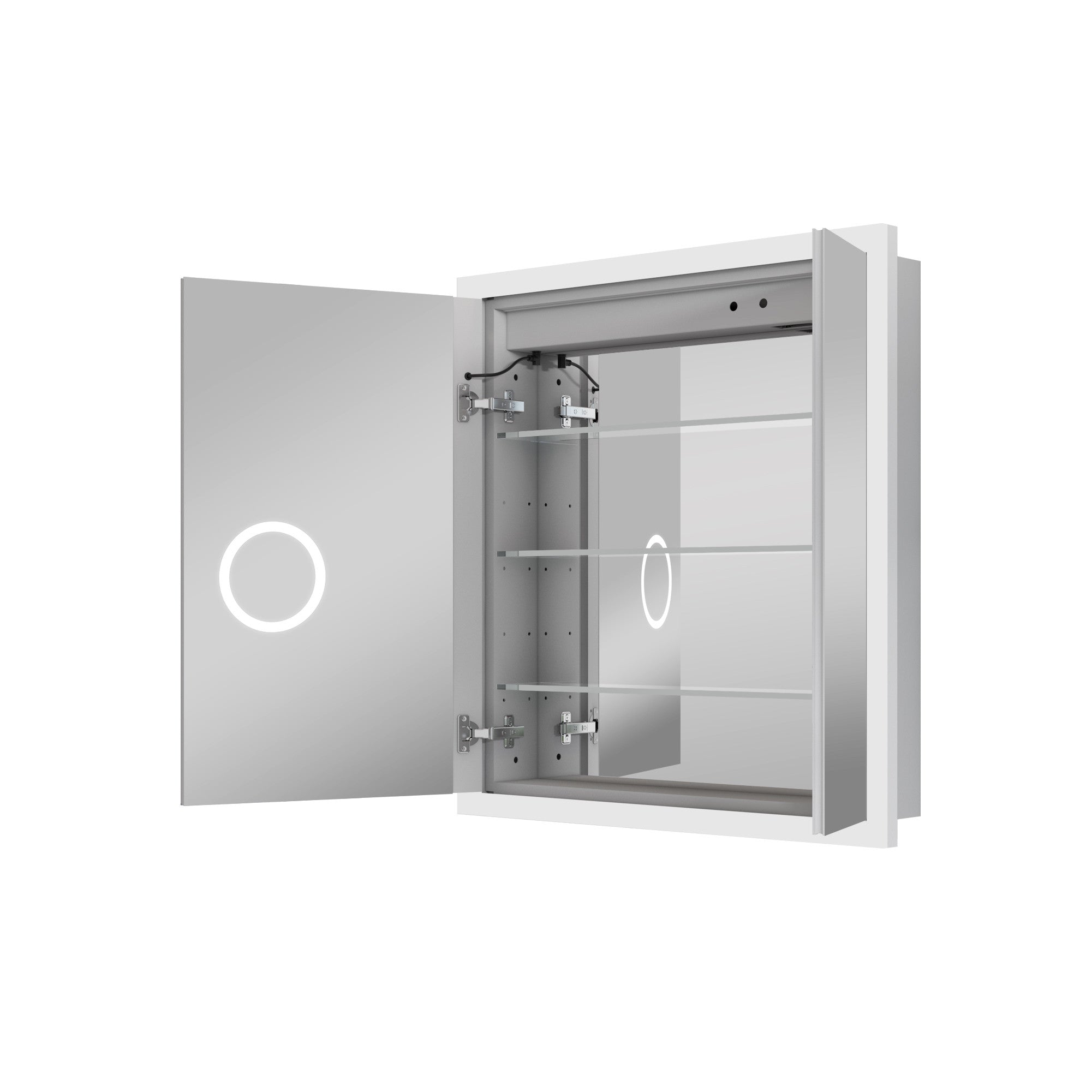
5.Redundancy in Heat Dissipation and Maintenance of Transformers (Drivers)
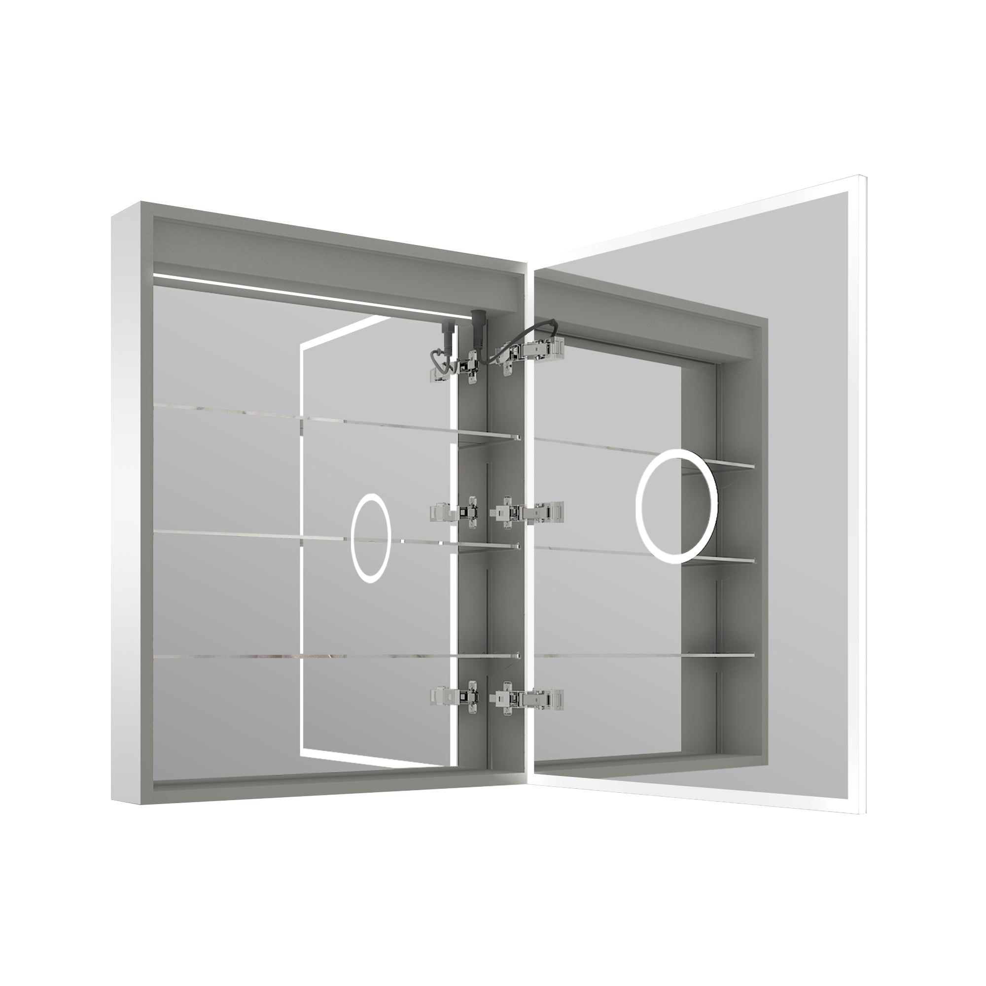
The core of the smart mirror is its driver, which converts 110V/220V AC power into 12V/24V low-voltage DC power.
Cooling space: A gap of at least 0.5-1 inch should be maintained behind the mirror. During electrical installation, do not haphazardly plug excess cables above the driver to prevent heat accumulation and shorten the LED's lifespan.
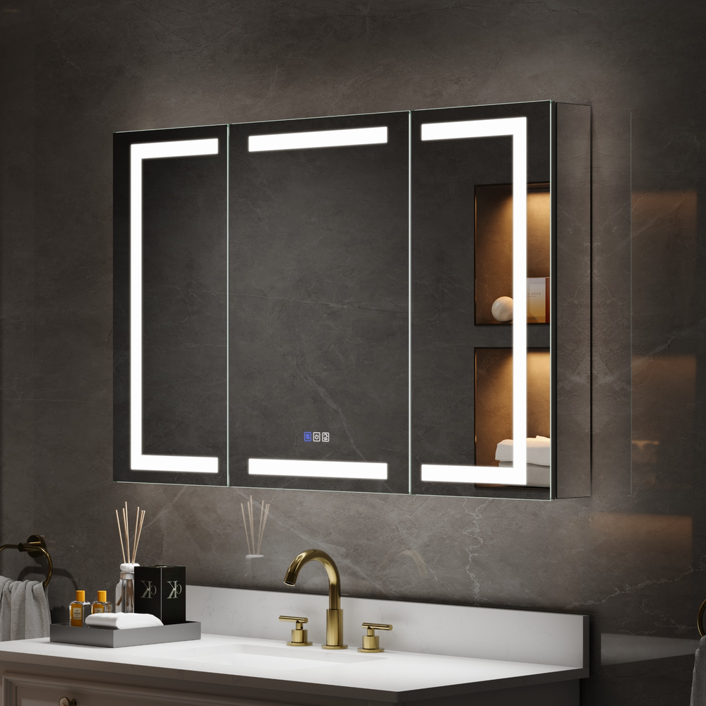
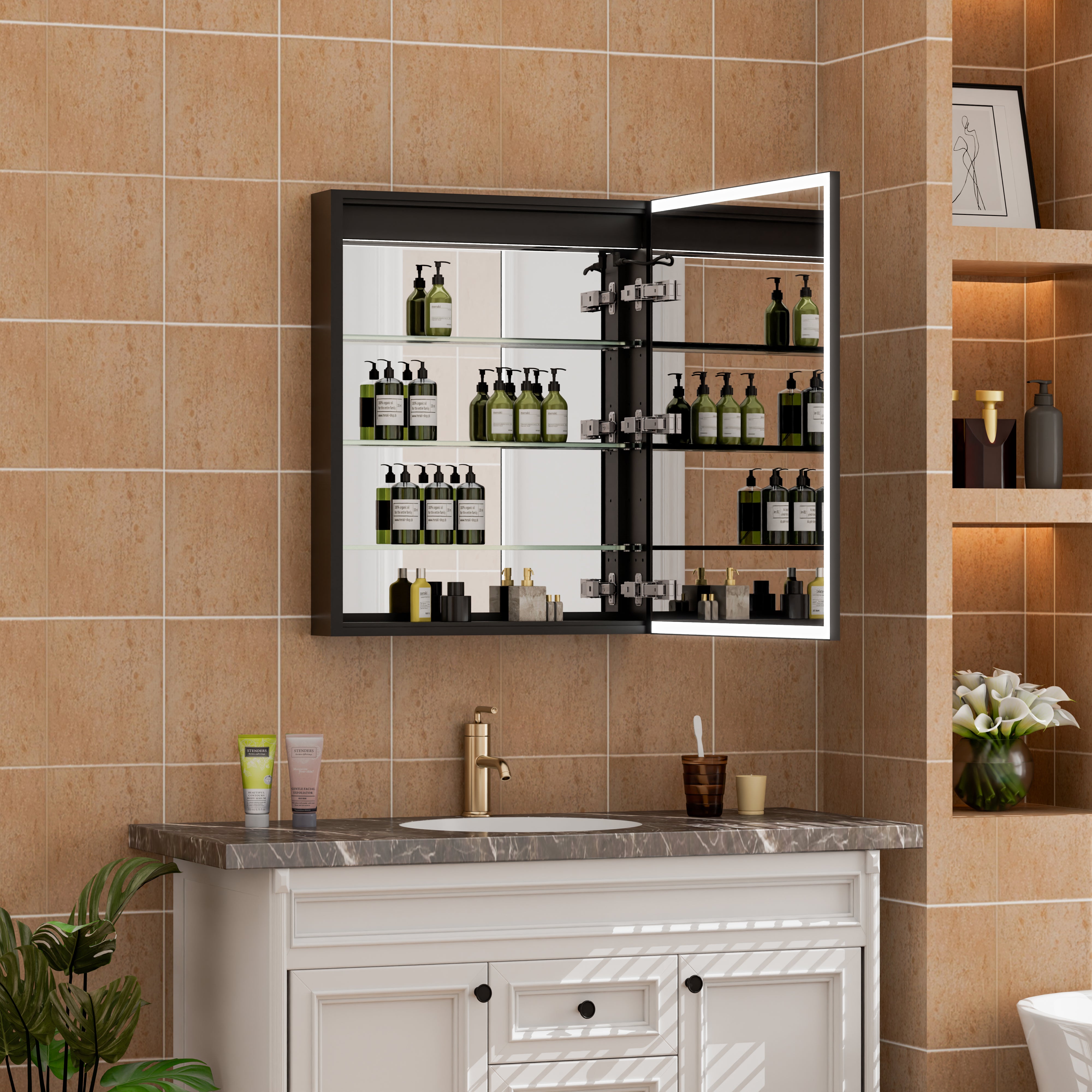
Consideration for inspection ports: For ultra-large embedded medicine cabinet mirrors (Recessed Medicine Cabinet), if the driver is not integrated with the mirror body, it is recommended to reserve inspection ports in the ceiling or side cabinet to facilitate the replacement of electronic components without dismantling the wall in the future.

6.Intelligent interaction integration: signal coverage of Zigbee and Bluetooth
The smart mirror of 2026 has become a node in smart homes.
Signal shielding: The large-area coating and aluminum alloy frame on the back of the mirror may shield wireless signals. When planning the electrical layout, the location of routers or smart gateways should be as close to the bathroom as possible, or a hidden Wi-Fi amplifier should be reserved on the bathroom ceiling to ensure smooth playback of mirror voice assistants (such as Gemini Link) and music streaming.
Dual mode power supply: Some high-end mirrors are equipped with memory batteries, so even if the wall switch cuts off the main Power, the clock and setting parameters inside the mirror will not reset.
7.Visual proportion and light path synergy: Say goodbye to glare and shadows
Electrical layout must serve visual effects.
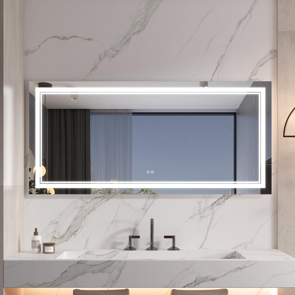
Auxiliary lighting coordination: The LED strip of the smart mirror is mainly used for "front light" for grooming purposes. The ceiling ambient lighting still needs to be retained in the electrical layout.
The logic of installation height: Combined with the Mirror Colors adjustment function mentioned earlier, the potential's accuracy determines the mirror's mounting height. If the potential is too high or too low, forcibly attaching it will cause the light path to deviate from the line of sight, resulting in unnatural shadows on the face.
Summary: Electrical Engineering - The "Invisible Skeleton" of Intelligent Mirrors
How to integrate LED smart mirrors into the electrical layout? This is not just a plug issue, but a system engineering effort focused on precise positioning, load calculation, safety compliance, and intelligent interaction.
In the context of the 2026 renovation, a well-designed electrical layout can make the smart mirror feel as natural as if it were "long" on the wall. Whether it's defogging in the morning, precise color rendering during grooming, or the warm, floating light at night, they are all built on a wire buried in the wall and positioned accurately at the early stage. By reserving GFCI protection, optimizing the heat dissipation space of the drive, and implementing wall switch linkage, you can ensure that the washroom remains at the peak of technology and safety for the next decade.


Leave a comment
This site is protected by hCaptcha and the hCaptcha Privacy Policy and Terms of Service apply.